5-Axis vs. 3+2: What the Difference Actually Means for Your Part
LightsOut CNC Journal · 6 min read
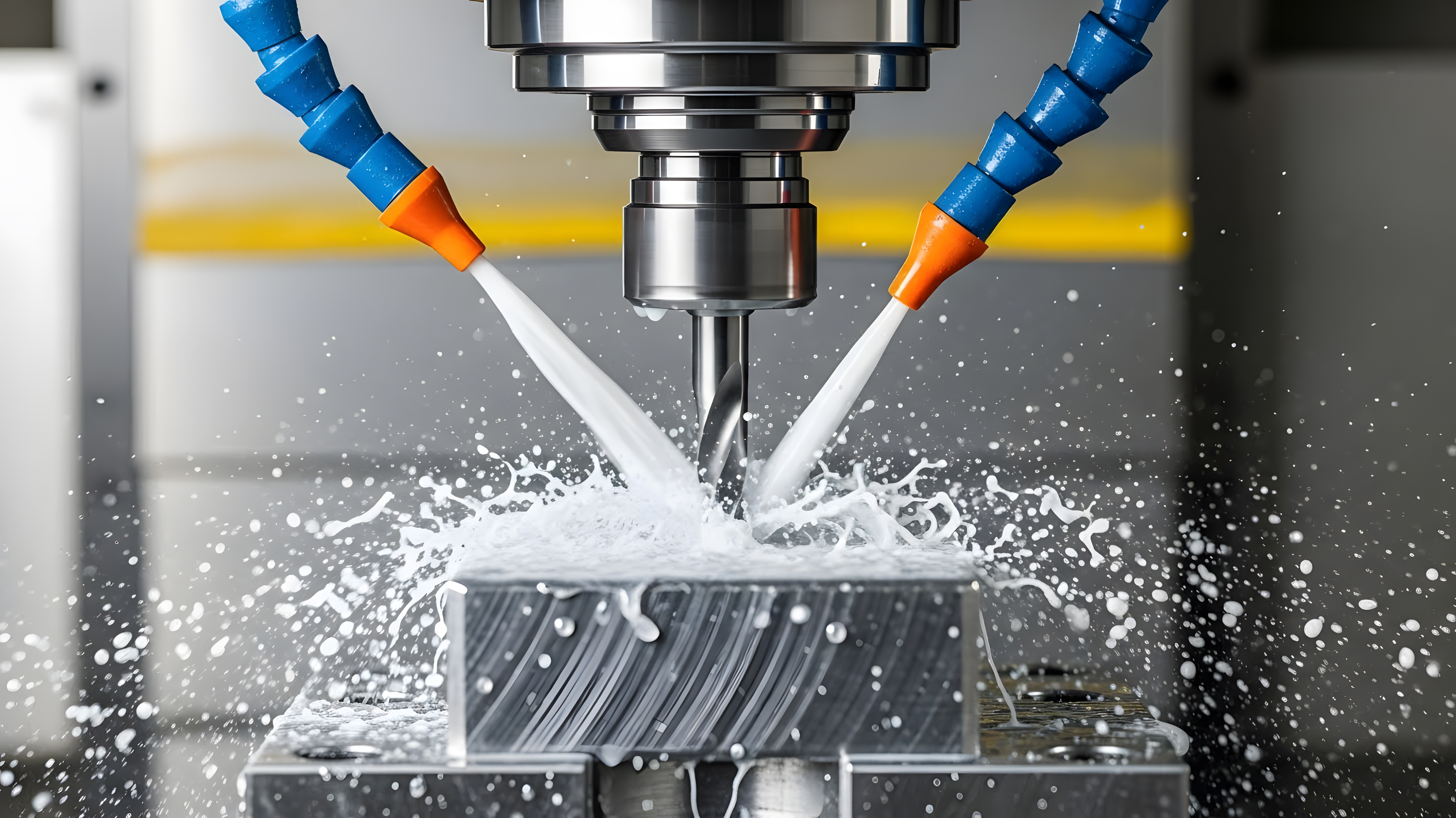
"5-axis machining" gets used as a catch-all term, but it actually describes two different capabilities that solve different problems. Both run on the same 5-axis machine tool. The difference is whether the two rotational axes move while the tool is cutting, or whether they simply reposition the part between cuts. Buyers who don't distinguish between the two can end up quoting — or getting quoted — the wrong process for the part in front of them.
3+2: five axes of access, three axes of motion at a time
In 3+2 machining (also called positional or indexed 5-axis), the two rotational axes — typically a trunnion or rotary table — move the part into a fixed compound angle, lock in place, and the machine then cuts using standard 3-axis motion (X, Y, Z) against that new orientation. Once the cut is finished, the machine can re-index to another angle and cut again, all in the same setup and often the same cycle.
This is the workhorse case for most bracket, housing, and structural aerospace parts. A part with features on four or five faces — mounting bosses on one side, a pocket on another, angled holes on a third — no longer needs to be manually re-fixtured and re-zeroed for each face. The machine simply rotates to the next face and keeps going. That alone eliminates most of the setup error that shows up when a part gets pulled off a vise, flipped, and re-clamped by hand.
Simultaneous 5-axis: all five axes moving together, mid-cut
True simultaneous (continuous) 5-axis machining keeps all five axes — X, Y, Z, plus the two rotary axes — moving together during the cut, constantly reorienting the tool relative to the part as it machines a surface. This is what makes it possible to hold a cutting tool at a consistent, optimal angle across a contoured or organic surface, rather than approaching it in a series of flat, stepped passes.
Simultaneous motion matters most on parts where the surface itself is the geometry that has to be right: impeller and turbine blade profiles, complex ducting, deep pockets with draft that a fixed tool angle can't reach without gouging, or thin-wall structures where keeping the tool perpendicular to the wall reduces deflection and chatter. It is a genuinely different — and more demanding — programming and verification problem than 3+2, because the tool path, tool holder, and part are all moving relative to each other continuously.
Why single-setup accuracy is the real payoff
Whether a job calls for 3+2 or simultaneous motion, the underlying advantage is the same: everything gets machined from one set of datums, in one work-holding setup. Every time a part is removed from a fixture and re-clamped, some amount of positional error gets reintroduced — even with careful technique. A 5-axis process that reaches every required face or surface without breaking the original setup is what makes it realistic to hold tolerances like ±0.0005" across features that would otherwise be split across two or three separate operations.
That is also why single-setup capability tends to matter more on a drawing with tight positional or true-position callouts between features on different faces — the tolerance stack-up from multiple setups can consume the entire tolerance band before the part is even finished.
What to specify — and what to ask a shop
If you're sourcing a part, the geometry usually answers the question for you:
- Flat or planar features on multiple faces, angled holes, or compound-angle pockets — 3+2 is typically the right and more economical process.
- Continuously curved or contoured surfaces, blade profiles, or geometry where tool orientation has to change smoothly along the cut — that calls for true simultaneous 5-axis.
- Tight positional tolerances between features on different faces — ask whether the shop can hold the part in a single setup for all of them, regardless of which motion type is used.
Our two Matsuura MX-330 machining centers support both indexed 3+2 positioning and true simultaneous 5-axis motion, so the choice between them is a process decision made for your part's geometry — not a capability constraint on our end.